Manual/Basic Mesh Tools
From BlenderWiki
Contents[hide] |
Basic Mesh Modelling
In this section we will describe some of the most common Mesh editing tools: Extrude, Spin, Spin Dup, Screw, Warp and To Sphere.
Each tool is described using a simple tutorial. Extrude is explained by going through a simple set of steps for making a sword. Spin is explained by making a simple wine glass. Spin Dup is explained by making the hour mark on a clock face. Screw is explained by literally making a screw. And finally Warp is explained by warping some 3D text.
Extrude
One tool of paramount importance for working with Meshes is the Extrude command (E).
This command allows you to create cubes from rectangles and cylinders
from circles, as well as easily create such things as tree limbs.
Although the process is quite intuitive, the principles behind Extrude are fairly elaborate as discussed below.
- First, the algorithm determines the outside edge-loop of the Extrude; that is, which among the selected edges will be changed into faces. By default, the algorithm considers edges belonging to two or more selected faces as internal, and hence not part of the loop.
- The edges in the edge-loop are then changed into faces.
- If the edges in the edge-loop belong to only one face in the complete mesh, then all of the selected faces are duplicated and linked to the newly created faces. For example, rectangles will result in cubes during this stage.
- In other cases, the selected faces are linked to the newly created faces but not duplicated. This prevents undesired faces from being retained 'inside' the resulting mesh. This distinction is extremely important since it ensures the construction of consistently coherent, closed volumes at all times when using Extrude.
- Edges not belonging to selected faces, which form an 'open' edge-loop, are duplicated and a new face is created between the new edge and the original one.
- Single selected vertices which do not belong to selected edges are duplicated and a new edge is created between the two.
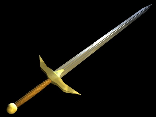
Grab mode is automatically started when the Extrude algorithm terminates, so newly created faces, edges, and vertices can be moved around with the mouse. Extrude is one of the most frequently used modelling tools in Blender. It's simple, straightforward, and easy to use, yet very powerful. The following short lesson describes how to build a sword using Extrude.
The Blade
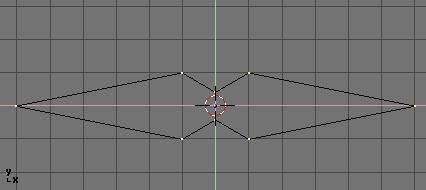
- Start Blender and delete the default plane. In top view add a mesh circle with eight vertices. Move the vertices so they match the configuration shown in Deformed circle, to become the blade cross section..
- Select all the vertices and scale them down with the S so the shape fits in two grid units. Switch to front view with NumPad 1.
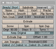
- The shape we've created is the base of the blade. Using Extrude we'll create the blade in a few simple steps. With all vertices selected press E, or click the Extrude button in the Mesh Tools Panel of the Editing Context (F9 - Extrude button in EditButtons context.).
- A box will pop up asking Ok? Extrude (Extrude confirmation box. ). Click this text or press Enter to confirm, otherwise move the mouse outside or press Esc to exit. If you now move the mouse you'll see that Blender has duplicated the vertices, connected them to the original ones with edges and faces, and has entered grab mode.
- Move the new vertices up 30 units, constraining the movement with Ctrl, then click LMB
 to confirm their new position and scale them down a little bit with the S (The Blade).
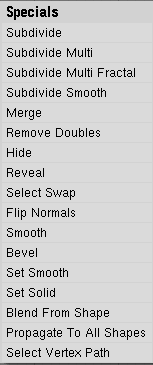
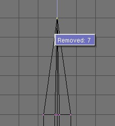
- Press E again to extrude the tip of the blade, then move the vertices five units up. To make the blade end in one vertex, scale the top vertices down to 0.000 (hold Ctrl for this) and press W>Remove Doubles (Mesh Edit Menu) or click the Rem Doubles button in the EditButtons (F9). Blender will inform you that it has removed seven of the eight vertices and only one vertex remains. The blade is complete! (The completed blade)
The Handle
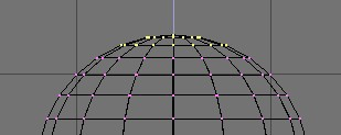
- Leave edit mode and move the blade to the side. Add a UVsphere with 16 segments and rings and deselect all the vertices with the A.
- Borderselect the top three rings of vertices with B and delete them with X>>Vertices (UV sphere for the handle: vertices to be removed ).
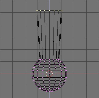
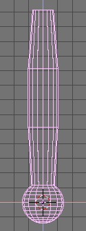
- Select the top ring of vertices and extrude them. Move the ring up four units and scale them up a bit (First extrusion for the handle), then extrude and move four units again twice and scale the last ring down a bit (Complete handle).
- Leave EditMode and scale the entire handle down so that it's in proportion with the blade. Place it just under the blade.
The Hilt
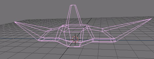
By now you should be used to the 'extrude>move>scale' sequence, so try to model a nice hilt with it. Start out with a cube and extrude different sides a few times, scaling them where needed. You should be able to get something like that shown in (Complete Hilt).
After texturing, the sword looks like (Finished sword, with textures and materials). As you can see, Extrude is a very powerful tool that allows you to model relatively complex objects very quickly; the entire sword was created in less than one half hour. Getting the hang of 'extrude>move>scale' will make your life as a Blender modeler a lot easier.Spin and SpinDup
Spin and Spin Dup are two very powerful modelling tools allowing you to easily create bodies of revolution or axially periodic structures.
Spin
Use the Spin
tool to create the sort of objects that you would produce on a lathe.
(This tool is often called a "lathe"-tool or a "sweep"-tool in the
literature, for this reason.)
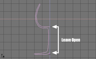
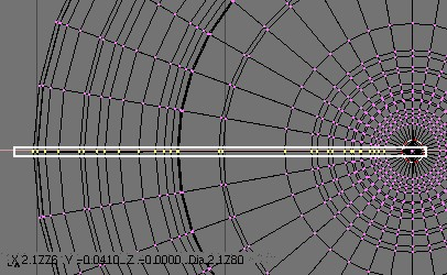
First, create a mesh representing the profile of your object. If you are modeling a hollow object, it is a good idea to thicken the outline. (Glass profile) shows the profile for a wine glass we will model as a demonstration.
In EditMode, with all the vertices selected, access the Editing Context (F9). The Degr button in the Mesh Tools panel indicates the number of degrees to spin the object (in this case we want a full 360° sweep).
The Steps button specifies how many profiles there will be in the sweep (Spin Buttons).
Like Spin Duplicate (discussed in the next section), the effects of Spin
depend on the placement of the 3D cursor and which window (view) is
active. We will be rotating the object around the cursor in the top
view. Switch to the top view with
NumPad 7.
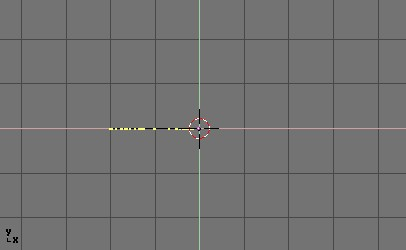
- Place the cursor along the center of the profile by selecting one of the vertices along the center, and snapping the 3D cursor to that location with Shift S → Cursor->Selection (Glass profile, top view in edit mode, just before spinning.) shows the wine glass profile from top view, with the cursor correctly positioned.
Before continuing, note the number of vertices in the profile.
You'll find this information in the Info bar at the top of the Blender
interface (Mesh data - Vertex and face numbers.).
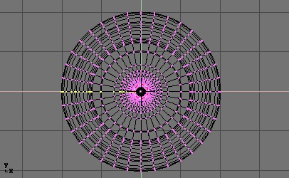
- Click the "Spin" button. If you have more than one window open, the cursor will change to an arrow with a question mark and you will have to click in the window containing the top view before continuing. If you have only one window open, the spin will happen immediately. Spinned profile shows the result of a successful spin.
- The spin operation leaves duplicate vertices along the profile. You can select all vertices at the seam with Box select (B) shown in (Seam vertex selection) and perform a Remove Doubles operation.
Notice the selected vertex count before and after the Remove Doubles operation (Vertex count after removing doubles.). If all goes well, the final vertex count (38 in this example) should match the number of the original profile noted in Mesh data - Vertex and face numbers.. If not, some vertices were missed and you will need to weld them manually. Or, worse, too many vertices will have been merged.
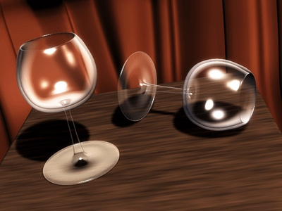
All that remains now is to recalculate the normals by selecting all vertices and pressing Ctrl N and selecting Recalc Normals Outside from the pop-up menu. At this point you can leave EditMode and apply materials or smoothing, set up some lights, a camera and make a rendering. (Final render of the glasses.) shows our wine glass in a finished state.
SpinDup
The Spin Dup
tool is a great way to quickly make a series of copies of an object
along a circle. For example, if you have modeled a clock, and you now
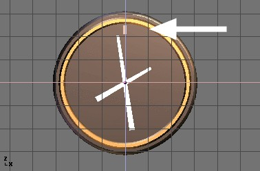
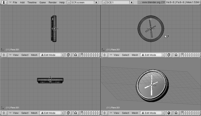
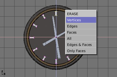
want to add hour marks. Model just one mark, in the 12 o'clock position
(Hour mark indicated by the arrow). Select the mark and switch to the Editing Context with F9.
Set the number of degrees in the Degr: NumButton in the Mesh Tools panel to 360. We want to make 12 copies of our object, so set the Steps to 12 (Spin Dup buttons).
- Switch the view to the one in which you wish to rotate the object by using the keypad. Note that the result of the Spin Dup command depends on the view you are using when you press the button.
- Position the 3D cursor at the center of rotation. The objects will be rotated around this point. Note: To place the cursor at the precise location of an existing object or vertex, select the object or vertex, and press Shift S → Cursor->Selection.
- Select the object you wish to duplicate and enter EditMode with Tab.
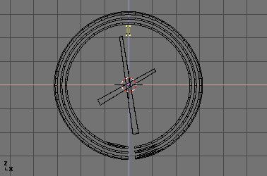
- In EditMode, select the vertices you want to duplicate (note that you can select all vertices with A or all of the vertices linked to the point under the cursor with L). See (Mesh selected and ready to be SpinDuped).
- Press the Spin Dup button. If you have more than one 3DWindow open, you will notice the mouse cursor change to an arrow with a question mark. Click in the window in which you want to perform your rotation. In this case, we want to use the front window (View selection for Spin Dup.).
If the view you want is not visible, you can dismiss the arrow/question mark with Esc until you can switch a window to the appropriate view with the keypad.
When spin-duplicating an object 360 degrees, a duplicate object is placed at the same location of the first object, producing duplicate geometry.
You will notice that after clicking the Spin Dup button, the original geometry remains selected. To delete it, simply press X → Vertices. The source object is deleted, but the duplicated version beneath it remains (Removal of duplicated object).
If you like a little math you needn't bother with duplicates because you can avoid them at the start. Just make 11 duplicates, not 12, and not around the whole 360°, but just through 330° (that is 360*11/12). This way no duplicate is placed over the original object.
In general, to make n duplicates over 360 degrees without overlapping, just spin one less object over 360*(n-1)/n degrees.
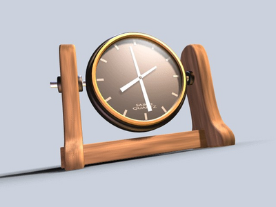
(Final Clock Render.) shows the final rendering of the clock.
Screw
The Screw tool combines a repetitive "Spin" with a translation, to generate a screw-like, or spiral-shaped, object. Use this tool to create screws, springs, or shell-shaped structures.
The method for using the "Screw" function is strict:
- Set the 3DWindow to front view (NumPad 1).
- Place the 3DCursor at the position through which the rotation axis must pass. Such an axis will be vertical.
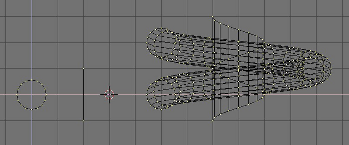
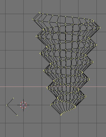
- Your mesh object must contain both the profile to be spun, as well as an open line of vertices to define the rotation axis. This open line can be a single edge, as shown in the figure, or a half circle, or whatever. You need only to ensure that there are two 'free' ends; two vertices belonging to a single edge linking then to another vertex. The Screw function localizes these two points and uses them to calculate the translation vector that is added to the "Spin" per each full rotation (How to make a spring: before (left) and after (right) the Screw tool.). If these two vertices are at the same location, this creates a normal "Spin". Otherwise, interesting things happen!
- Select all vertices that will participate in the "Screw".
- Assign the NumButtons Steps: and Turns: in the Mesh Tools Panel the desired values. Steps: determines how many times the profile is repeated within each 360° rotation, while Turns: sets the number of complete 360° rotations to be performed.
- Press Screw
If there are multiple 3DWindows, the mouse cursor changes to a question mark. Click on the 3DWindow in which the Screw
is to be executed. If the two "free" ends are aligned vertically the
result is the one seen above. If they are not, the translation vector
remains vertical, equal to the vertical component of the vector joining
the two 'free' vertices, while the horizontal component generates an
enlargement (or reduction) of the screw as shown in (Enlarging screw (right) obtained with the profile on the left.).
Warp Tool
The Warp tool is a little-known tool in Blender, partly because it is not found in the Edit Buttons window, and partly because it is only useful in very specific cases. At any rate, it is not something that the average Blender-user needs to use every day.
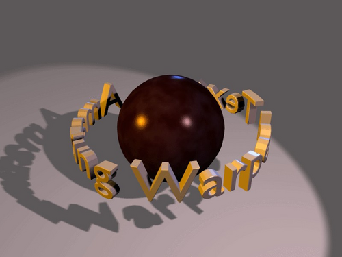
A piece of text wrapped into a ring shape is useful when creating flying logos, but it would be difficult to model without the use of the warp tool. For our example, we'll warp the phrase "Amazingly Warped Text" around a sphere.
- First add the sphere.
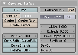
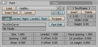
- Then add the text in front view, in the Editing Context and Curve and Surface Panel set Extrude to 0.1 - making the text 3D, and set Bevel Depth to 0.01, adding a nice bevel to the edge. Make the Bev Resol 1 or 2 to have a smooth bevel and lower the resolution so that the vertex count will not be too high when you subdivide the object later on using (Curve and Surface and Font) panels.
- Convert the object to curves, then to a mesh, (Alt C twice) because the warp tool does not work on text or on curves.
- Subdivide the mesh twice (W → Subdivide Multi → 2), so that the geometry will change shape cleanly, without artifacts.
 Font. |
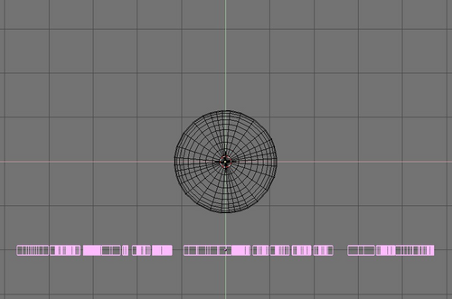
Switch to top view and move the mesh away from the 3D cursor. This distance defines the radius of the warp. (See Top view of text and sphere.)
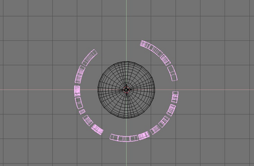
Place the mesh in Edit Mode (Tab) and press A to select all vertices. Press Shift W to activate the warp tool. Move the mouse up or down to interactively define the amount of warp. (Warped text). Holding down Ctrl makes warp change in steps of five degrees.
Now you can switch to camera view, add materials, lights and render (Final rendering).
|
To Sphere
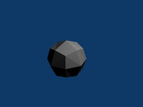
Another of the lesser known tools is To Sphere (Ctrl Shift S). This command allows the creation of spheres from subdivided cubes.
First, start with a Cube. I will start with from fresh by Erasing All (Ctrl X).
- Press Tab to switch into Edit Mode.
- Make sure all the vertices of the cube are selected by pressing A twice. Then, go to the Editing Panel by pressing F9. You should be able to see the Mesh Tools section now.
- Subdivide the cube by pressing the Subdivide button in the Mesh Tools section, or by pressing W and clicking "Subdivide". You can do this as many time as you want; the more you subdivide, the smoother your sphere will be.
- Click the To Sphere button now in the Mesh Tools. Select "100" to make your sphere. Alternatively, you can press Ctrl Shift S and type in "1.000" to achieve the same effect.
The completed sphere!
Categories: Blender 2.40 | Meshes | Basics | Tools | Mesh tools
