Manual/Edge and Face Tools
From BlenderWiki
Contents[hide] |
Edge and Face Tools
Mode: Edit Mode (Mesh)
Hotkey: Ctrl E or K
Menu: Mesh → Edges
Description

A key issue in modelling is the necessity to add vertices in certain
zones of the mesh, and this is often regarded as splitting, or adding,
edges in a given region. Many Edge Tools are grouped in a menu which is
linked to K hotkey (Loop/Cut Menu.), but each individual tool has its own hotkey as well.

Edge Tools for selection and manipulation are grouped in a menu which is linked to Ctrl E hotkey (Edge Specials Menu.).
Edge Slide, for example, slide the vertices in the loop along
the edges. If you select a loop on an egg-shaped object, for example,
sliding the vertices will move them, not left/right or up/down, but
instead proportionally move them as if they were sliding along the edge
using the edge as a guide. More information on selecting loops is found
below.
Edge Selection
Mode: Edit Mode (Mesh)
Hotkey: RMB ![]()
Description

In Edit Mode there are a few ways to select edges: implicitly, explicitly, looping or by Region Selection. Implicit means you describe a more complex element using less complex elements. For example, to describe an edge you need to specify two vertices and to describe a face you need to specify three or more vertices or three or more edges.
Region Selection is a tool that allows selection of edges and faces based on an intersection with a circular 2D region.
- Explicit Edge Selection
- To select an edge use edge select mode and RMB
 click on an edge. To select additional edges use Shift RMB .
- Implicit Edge Selection

- The other way to select an edge is to select two vertices that
bound the edge of interest. You are implying which edge by selecting
its bounding vertices. To select an edge implicitly use vertex select mode in combination with RMB and/or Shift RMB .
- In (Implicit Edge selection), the cube on the left shows an edge selected using vertices. The cube on the right is what shows when you switch to edge select mode.
Options
If you are in solid, shaded, or textured viewport shading mode (not bounding box or wireframe), you will have a fourth button that looks like a cube. When enabled, this limits your ability to select based on visible edges (as if the object was solid), and prevents you from accidentally selecting, moving, deleting or otherwise working on backside or hidden edges.
Edge Loop Selection
Mode: Edit Mode (Mesh) > Vertex Select Mode or Edge Select Mode
Hotkey: Alt RMB ![]() or Ctrl E, 7 (based on existing edge selection)
or Ctrl E, 7 (based on existing edge selection)
Menu: Select → Edge Loop (based on existing edge selection)
Description
Holding Alt while selecting an edge selects a loop of edges that are connected in a line end to end, passing through the edge under the mouse pointer. Holding Shift while clicking adds to the current selection. Edge loops can also be selected based on an existing edge selection, using ‘Edge Loop Select’ in the Edge Specials menu.
Examples

The left sphere shows an edge that was selected longitudinally. Notice how the loop is open. This is because the algorithm hit the vertices at the poles and terminated because the edge at the pole connects to more than 3 other edges. However, the right sphere shows an edge that was selected latitudinally and has formed a closed loop. This is because the algorithm hit the first edge that it started with.
Technical Details
The algorithm for selection is as follows:
- First check to see if the selected element connects to only 3 other edges.
- If the edge in question has already been added to the list, the selection ends.
- Of the 3 edges that connect to the current edge, the ones that share a face with the current edge are eliminated and the remaining edge is added to the list and is made the current edge.
See Also
Edge Ring Selection
Description
In edge select mode, holding Ctrl Alt while selecting an edge selects a sequence of edges that are not connected, but on opposite sides to each other continuing along a face loop. Using the same command in vertex select mode will select such a face loop implicitly.
Examples

In (A selected edge loop, and a selected edge ring), the same
edge was clicked on but two different "groups of edges" were selected,
based on the different commands. One is based on edges during
computation and the other is based on faces.
Technical Details
Edge ring selection is based on the same algorithm as in Face Loop Selection, though the end results differ as only edges are selected.
Face Selection
Mode: Edit Mode (Mesh)
Hotkey: RMB ![]()
Description
In EditMode there are a few ways to select Faces: implicitly, explicitly, looping or by region. Implicit means you describe a more complex element using less complex elements. For example, to describe an edge you need to specify two vertices and to describe a face you need to specify three or more vertices or three or more edges.
- Explicit Face Selection
- To select a face use Face select mode (Select modes.) and the RMB . To select additional faces use Shift RMB .
- Implicit Face Selection
-
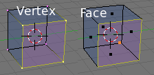 Implicit Face selection.

Selecting the three or four vertices that bound the face of interest in vertex select mode selects it implicitly. (Implicit Face selection) shows a face selected on a cube using vertices the cube of the left. The cube on the right is what shows when you switch to Face select mode.
You can also implicitly select faces by selecting the bounding edges of the face of interest. This will produce the same results as selecting vertices.
Options
If you are in solid, shaded, or textured viewport shading mode (not bounding box or wireframe), you will have a fourth button that looks like a cube. When enabled, this limits your ability to select from visible faces (as if the object was solid), and prevents you from accidentally selecting, moving, deleting or otherwise working on backside or hidden faces.
Face Loop Selection
Mode: Edit Mode (Mesh) > Face Select Mode or Vertex Select Mode
Hotkey: Alt RMB ![]() (face select mode) or Ctrl Alt RMB
(face select mode) or Ctrl Alt RMB ![]() (vertex select mode)
(vertex select mode)
In face select mode, holding Alt while selecting an edge selects a loop of faces that are connected in a line end to end, along their opposite edges. In vertex select mode, the same can be accomplished by using Ctrl Alt to select an edge ring, which selects the face loop implicitly.
Examples

This face loop was selected by clicking with Alt RMB ![]() on an edge, in face select mode. The loop extends perpendicular from the edge that was selected.
on an edge, in face select mode. The loop extends perpendicular from the edge that was selected.

A face loop can also be selected in Vertex select mode, see (Alt versus Ctrl-Alt in Vertex Mode). The edges selected in the grid labeled "Alt-RMB" is a result of selecting and edge loop versus selecting an edge ring. Because in Vertex Select Mode, selecting opposite edges of a face implicitly selects the entire face, the face loop has been selected implicitly.
Note that in these cases the generated result of the algorithm was vertices because we were in Vertex select mode. However, had we had been in Edge select mode the generated result would have been selected edges.
Technical Details
The algorithm for selection is as follows:
- A face loop is made by two neighbouring edge loops.
- Extends only to quadrilateral faces.
- Ends when a triangular face is met (and the two bounding edgeloops merge into one).
Loop Subdivide
Description
Loop Subdivide splits a loop of faces by inserting a new edge loop intersecting the chosen edge. The tool is interactive and has two steps:
- 1. Previsualising the cut
- The cut to be made is marked with a magenta coloured line as you move the mouse over the various edges. In (Pre-visualising the cut), the mouse cursor was located where the white circle is located. This caused the loop line to appear at the mid point of the edge. The to-be-created edge loop stops at the poles where the existing face loop terminates.
- 2. Sliding the new edge loop
- Once an edge is chosen via LMB
 , that edge is highlighted in green (Loop Split edge selected) and you can move the mouse along the edge to determine where the new edge loop will be placed. This is identical to the Edge Slide tool. Clicking LMB again confirms and makes the cut at the pre-visualised location, or clicking MMB
  forces the cut to exactly 50%.
- (Loop Split edge completed) shows the new faces and edges, A and B. The view is rotated so that the new faces and edges are clearly visible from the top of the sphere.
 Pre-visualising the cut |  2. Sliding the new edge loop |  3. Loop Split edge completed. |
Options
- 1. Previsualising the cut
- Upon initial activation of the tool 3D window header changes to show the "Number of Cuts" (Initial Loop Split header). Entering a number with the keyboard, scrolling MW
 or using NumPad + and NumPad - changes the number of cuts (maximum of 130). These cuts run parallel with the face loop line.
- S changes the cut to 'smooth' mode. By default, new vertices for the new edge loop are placed exactly on the pre-existing edges. This keeps subdivided faces flat, but can distort geometry, particularly when using Subdivision Surfaces. If smooth mode is on then new vertices are not placed on the previous edge but shifted outwards by a given percentage, similar to the 'Subdivide Smooth' command.
- 2. Sliding the new edge loop
- P switches between Proportional and Percentage modes. The default mode is Percentage.
- In Proportional mode, MW , or ← and → changes the selected edge for calculating a proportion.
- Holding Ctrl or SHIFT control the precision of the sliding. Ctrl snaps movement to 10% steps per move and Shift snaps movement to 1% steps. The default is 5% steps per move.
Examples

In order to explain Proportional and Percentage modes we can use a very simple mesh layed out like a 2x9 grid, (Loop Example Grid). The vertices at A and D have been moved in order to emphasize the difference between the two modes. The vertices at the level C and B remain unchanged. E is an area of interest when looking at Proportional mode.
Percentage mode
In Percentage mode the 3D window header changes to (Percentage header) showing a number between -1 and 1 with 0 representing 50% or midway between.
As you move the mouse the percentage changes and the edge loop line, drawn in yellow, moves as a percentage of the distance between the edge marked in green as shown in (25% between), (Mid-way) and (89% between).
 25% between |  Mid-way |  89% between |
The yellow loop line is always the same percentage along edge of the edges that are being cut, regardless of the edges' lengths. For example, in (Mid-way) the yellow loop line is exactly halfway between vertex A and B and it is also exactly halfway between vertex C and D. For (25% between) you can see that the yellow line loop is always 25% along each of the cut edges.
Proportional mode
Proportional face loop splitting keeps the shape of the newly cut edge loop the same as one of the edge loops that it cuts between, rather than cutting at a percentage along each perpendicular edge.
In Proportional mode the 3D window header changes to (Proportional header) showing the position along the length of the currently selected edge which is marked in green. Movement of the sliding edge loop is restricted to this length. As you move the mouse the length indicator in the header changes showing where along the length of the edge you are.
Unlike Percentage mode, Proportional mode treats the edge as having a start and end vertex with the start marked by a magenta marker (Vertex Marker). The start vertex (A), can be flipped to the opposite vertex using F (Vertex Marker Opposite).
 Vertex Marker. |  Vertex Marker Opposite. |
Moving the mouse moves the cut line towards or away from the start vertex, but the loop line will only move as far as the length of the currently selected edge, conforming to the shape of one of the bounding edge loops.
(Proportional Range) shows an example of how the distance is restricted by the length of the current edge (B). Looking at (A), you can see that the line loop has moved the same distance. If the line only moves 0.2 units on the selected edge then the line only moves 0.2 units everywhere else in the face loop region. The portion of the line loop at A hasn't gone all the way to the "bottom" because the selected edge is only 0.25 units in length. The line portion at "A" will not be able to move more than 0.25 units down because the range of movement is restricted to the length of the selected edge.
 Proportional Range |
(Proportional Range Flipped) is another example where the start vertex has been flipped while using the same selected edge as compared to (Proportional Range). You can see that movement is still restricted to the length of the selected edge. The yellow edge loop line stays straight, conforming to the bottom bounding edge loop because the cut is placed a constant distance from the bottom edge loop, along the crossed edges.
 Proportional Range Flipped |
Delete Edge Loop
Description

Delete Edge Loop allows you to delete a selected edge loop if it is between two other edge loops. This will create one face-loop where two previously existed.
| Note: The Edge Loop option is very different to the Edges option, even if you use it on edges that look like an edge loop. Deleting an edge loop merges the surrounding faces together to preserve the surface of the mesh. By deleting a chain of edges, the edges are removed, deleting the surrounding faces as well. This will leave holes in the mesh where the faces once were. |
Limitations & Work-arounds
For Edge Loop Delete to work correctly, a single edge loop must be selected. The same restrictions as those of Edge Slide apply, see Edge Slide for more details.
Examples
The selected edge loop on the UV Sphere has been deleted and the faces have been merged with the surrounding edges. If the edges had been deleted by choosing "Edges" from the (Erase Menu) there would be an empty band of deleted faces all the way around the sphere instead.
 Before Delete Edge Loop |  After Delete Edge Loop |
Knife Subdivide
Mode: Edit Mode (Mesh)
Panel: Editing Context → Mesh Tools
Hotkey: Shift K
Menu: Mesh → Edges → Knife Subdivide...
Description
Knife Subdivide subdivides selected edges intersected by a user-drawn 'knife' line. For example, if you wish to cut a hole in the front of a sphere, you select only the front edges, and then draw a line over the selected edges with the mouse. The tool is interactive, and only works with edges; selected either implicitly or explicitly.
Options
- Cut Types

- The Knife Subdivide menu presents the following cut types:
- Exact Line divides the edges exactly where the knife line crosses them.
- Midpoints divides an intersected edge at its midpoint.
- Multicut makes multiple parallel cuts. An additional number input is presented, allowing you to select the number of cuts.
- Drawing the cut line
- When using Knife Subdivide, the cursor changes to an icon of a scalpel and the 3D View header shows (Knife Tool 3DWindow header). You can draw connected straight lines by clicking LMB and moving repeatedly or you can create freehand lines by pressing and holding LMB while dragging. MMB constrains the cut line to a vertical or horizontal screen axis.
- Confirming and selection
- Pressing Esc or RMB at any time cancels the tool, and pressing Enter confirms the cut, with the following options:
- Enter will leave selected every edge except the new edges created from the cut.
- Ctrl Enter will select only the new edges created from the cut. Note: only edges that intersect the hand-drawn selected edges will be selected.
-
 Knife Tool 3DWindow header
- Topology
- Knife subdivide uses the same options as the other subdivide tools, located in the Edit Buttons. If the Beauty option is toggled selected faces are only subdivided along the longest 2 sides. If both Beauty and Short options are toggled, selected faces are only subdivided along the shortest 2 sides.
- Note: Using edge select mode to select only the edges you wish to subdivide creates a more accurate subdivision than using the "Beauty" toggle.
Examples
Exact Line Cut Type
(Exact Line before and after) is an example of using the 'Exact Line' knife. The cut is determined from the hand-drawn line labeled A in the plane labeled "Drawing".
The plane labeled "Enter" is the result of hitting the Enter key. The intersections on the edges of the plane are where the drawn line actually intersects, no matter how wiggly the line is. In addition, all the edges have been selected other than the newly created edges from the cut tool itself.
The plane labeled "Ctrl-Enter" is the result of hitting Ctrl Enter. In this case only the newly created edges, B and C, are selected while edge D is not. D is a secondary edge added as a side effect of the cut tool.

Midpoints Cut Type
(Midpoints before and after) is an example of using the 'Midpoints Line' knife. The cut is determined from the hand-drawn line labeled A on the plane labeled "Drawing". Notice how the line labeled A intersects the right edge twice; only the first intersection will be considered during the cut.
The plane labeled "Enter" is the result of hitting Enter. The intersections on the edges of the plane are the mid points of each edge, regardless of where the line was drawn. All the edges have been selected other than the newly created edges from the cut tool itself.
The plane labeled "Ctrl-Enter" is the result of hitting Ctrl Enter. In this case only the newly created edges, B and C, are selected while edge D is not. D is a secondary edge as a result of the cut tool.

MultiCut Type
This cut type presents a popup dialog appears asking for the Number of Cuts, which defines how many equally spaced cuts the tool should make for each intersecting edge. For example, the default of "2" generates two intersections or three new edges for each intersection of the hand-drawn line.
(MultiCut before and after) is an example of using the 'MultiCut' knife. The cut is determined from the hand-drawn line (A) on the plane labeled "Drawing", while using the default "2" as the number of cuts. The line was drawn so that it deliberately intersected three edges.
The grid labeled "Enter" is the result of hitting Enter. There are two cuts equally spaced on each edge intersected by the hand-drawn line; labeled A, B and C. D is a secondary edge as a result of the cut tool. The grid labeled "Ctrl-Enter" is the result of hitting Ctrl Enter. In this case only the newly created edges are selected while edge D is not.

Limitations & Work-arounds
The cut lines can be drawn with any number of segments, but only one intersection is detected one crossing per edge. Crossing back over an edge multiple times does not perform additional cuts on it.
Snap to grid is not currently implemented, but is being looked at for future releases.
Optimizations
With a large mesh, it will be quicker to select a smaller number of vertices, those defining only the edges you plan to split since the Knife will save time in testing selected vertices for knife trail crossings.
Rotate Edge CW / Rotate Edge CCW
Mode: Edit Mode (Mesh)
Hotkey: Ctrl E, 3 and Ctrl E, 4
Menu: Mesh → Edges → Rotate Edge CW / Rotate Edge CCW
Description
Rotating an edge clockwise or counter-clockwise spins an edge between two faces around their vertices. This is very useful for restructuring a mesh's topology. The tool can operate on one explicitly selected edge, or on two selected vertices or two selected faces that implicitly select an edge between them.
Examples

Be aware that sometimes, as shown in (Selected Edge Rotated CW and CCW, indicated with a T, that you could produce what appears to be "T" junctions/nodes by using this tool. However, Blender has created additional edges that prevent cracks in the mesh. You can test this by selecting the vertex at the T and moving it around while noting that there are two edges now instead of one long edge.

To rotate an edge based on faces you must to select two faces, (Adjacent selected Faces), otherwise Blender notifies you with an error dialog, "ERROR: Select one edge or two adjacent faces." Using either Rotate Edge CW or Rotate Edge CCW will produce exactly the same results as if you had selected the common edge shown in (Selected Edge Rotated CW and CCW.).
Edge Slide
Mode: Edit Mode (Mesh) > Vertex Select Mode or Edge Select Mode
Hotkey: Ctrl E, 6
Menu: Mesh → Edges → Slide Edge
Description
Edge Slide slides one or more edges along faces adjacent to the selected edge(s) with a few restrictions involving the selection of edges.
Options
- LMB confirms the tool, and RMB or Esc cancels
- As with Loop Subdivide, this tool has both a Percentage and Proportional mode, which is displayed in the 3D View header. These modes behave the same as in Loop Subdivide including all keys for controlling precision edge movement.
Examples

(Simple edge slide) is an example of sliding an edge along an extruded box. The selected edge is labeled E and the adjacent faces to that edge are F1 and F2. In Edge moving, the edge is being slid along the edge drawn in green. Moved shows the results.
Limitations & Work-arounds
There are restrictions on the type of edge selections that can be operated upon. Invalid selections are:
- Loop crosses itself
- This means that the tool could not find any suitable faces that were adjacent to the selected edge(s). (Loop Crosses) is an example that shows this by selecting two edges that share the same face. A face can not be adjacent to itself.
- Was not a single edge loop
- Most likely you have selected edges that don't share the same edge loop. (Single Edges) is an example where the selected edges are not in the same edge loop which means they don't have a common edge. You can minimize this error by always selecting edges end to end or in a "Chain".
- Could not order loop
- This means the tool could not find an edge loop based on the selected edge(s). (Order loop) is an example where a single edge was selected in a 2D Plane object. An edge loop can not be found because there is only one face. Remember, edge loops are loops that span two or more faces.
 Loop Crosses. |  Single Edges. |  Order loop. |
A general rule of thumb is that if multiple edges are selected they should be connected end to end such that they form a continuous chain. This is literally a general rule because you can still select edges in a chain that are invalid because some of the edges in the chain are in different edge loops. (Loop Crosses) is just such an example where the selected edges form a chain but they are not in the same edge loop.
If you select multiple edges just make sure they are connected. This will decrease the possibility of getting looping errors.
Bevel
Description

A bevel is something that smooths out a sharp edge or corner. True world edges are very seldom exactly sharp. Not even a knife blade edge can be considered perfectly sharp. Most edges are intentionally bevelled for mechanical and practical reasons.
Bevels are also useful for giving realism to non-organic
models. In the real world, the blunt edges on objects catch the light
and change the shading around the edges. This gives a solid, realistic
look, as opposed to un-bevelled objects looking false.
Options
- Recursion
- The number of recursions in the bevel can be defined in an additional popup number field. The greater the number of recursions, the smoother the bevel.
- If it is one, then each face is reduced in size and each edge becomes a single new face. Tri and Quad faces are created as necessary at the corresponding vertices. If the Recursion number is greater than one, then the bevel procedure is applied that number of times. Hence, for a Recursion of 2 each edge is transformed into 4 edges, three new faces appear at the edge while smoothing the original edge. In general the number of new edges is 2 elevated to the Recursion power.
- Width
- You can change the bevel width by moving the mouse towards
and away from the object. The scaling can be controlled to a finer
degree by either holding Ctrl, to scale in 0.1 steps, or by holding Shift to scale in 0.001 steps. LMB finalizes the operation, RMB or Esc aborts the action.
- Alternatively, you can manually enter a scaling value by pressing Space. A popup dialog appears, , asking you to type in the beveling scale factor labeled as "Width". The scale is limited to a range from 0.0 to 10.0 and upon hitting "OK" the bevel action is completed.
-
 Bevel window header.
Hints
Remember that in each recursion, for each new edge two new vertices are created, with additional vertices created at the intersection between edges. This means your vertex count can quickly become enormous if you bevel with a high recursion!
A Bevel, applied to a Curve object, forms a skin for the curve, like the outside of a cord, or hose pipe. Normally the Bevel is round like a pipe or soda can, but it can be rectangular for simulating wrought iron, oval with a crease for a power cord, star-shaped for a shooting star illustration; anything that can be physically formed by extrusion (extruded).
A Taper, applied to a Beveled Curve, changes the diameter of the Bevel along the length of the curve, like a python just having eaten a rat, or like a hose bulging up under pressure, or a vine growing.
Bevel Selected Edges
With the W->Bevel command, all edges of a given mesh are bevelled. To bevel only selected edges, use the Bevel Center script instead.
Examples
(Bevelling a cube) is an example of bevelling a cube with a Recursion of 2. Once the Recursion number is set each face of the mesh receives a yellow highlight. The cube labeled Bevelling is the tool in action.
The final result can be seen in the grid labeled "Beveled" or "Shaded".

|
