Manual/Material Nodes
From BlenderWiki
Contents[hide] |
Please be sure to read Manual/Node Materials before reading this page.
The material nodes allow you to manipulate a material by routing it through a map of connected nodes. A starting material is routed through different nodes that do various things to the material, combined with other inputs or put back together, and finally output where it can be applied to a mesh, halo, particle, etc.
Materials can be split into their RGB components, combined (mixed) with other inputs, and layered on top of one another. In the real world, this process is accomplished by mixing specific paints, thinners, surface prep, and then painting using various techniques under environmental conditions.
This section is organized by type of node, which are grouped based on similar functions:
- Input - Introduces a material or component to the node map.
- Output - Displays the result in progress as a small image.
- Color - Manipulates the colors of the material.
- Vector - Change the way light is reflected off the material.
- Convertors - Convert colors to other material colors.
- Groups - User-defined groups of nodes.
The simplest way to add a node is to put your cursor in a Node Editor window, and then press Space and click on Add.
The popup menu will extend to show you these types of nodes. Click on a
node type and the popup menu will extend again to show you specifc node
types available.
Material Input Nodes
A starting material is created in the Materials Panel. The Nodes button is enabled to add that material to the list of noded materials shown in the Node Editor window header. Other inputs to the node map include:
- A value
- A color
- A texture
- Geometry
Material Node
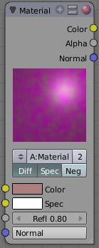
The Material node is used to add a material to the node program. Materials can be anything from pure shading to fully layered with textures. It inputs the main attributes of a material (color, alpha and normal vector) into the map.
Output
Materials can output color (which includes shading and any textures assigned to it), alpha, and the final normal calculated from any textures it has.
- Color
- Alpha
- Normal
Input
Materials can take inputs for colors, inputs for diffuse color and specularity color, a value for reflectivity, and a normal.
- Color - The base color of the paint. Can be set
- Spec - The color that is reflected as you get perpendicular to the light source reflecting off the surface. The color can be
- Refl: - The degree to which the material reflects light and gives off its color. The value can be provided by another node or set manually.
- Normal - The lighting condition.
Controls
- MA:Material field
- You can browse and select materials here.
- Diff toggle
- Turn on/off Diffuse Color.
- Spec toggle
- Turns on/off Specularity calculation.
- Neg toggle
- Inverts the material input normal when activated (which, of course, is a combination of the 3D normal given to it by the 3D object plus the normal input point).
| Normal Override: The normal input socket does not in any way blend the source normal with the underlying geometry. Any plugged in Geometry here overrides the Normal lighting conditions. |
Using the Material Node with Specularity
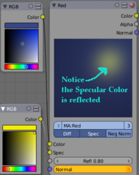
To make a material node actually generate a color, you have to specify at least a basic input color, and optionally a specularity color. The specularity color is the color that shines under intense light.
For example, consider the mini-map to the right. The base color, a dark blue, is connected from an RGB color generator node to the Color input socket. The specular color, yellow, is connected to the Spec input. Under Normal lighting conditions on a flat surface, this material will produce a deep blue color and, as you approach a spot perpendicular to the light, you will see the yellow specular color mix in.
| Enable Spec: To see specularity, you have to enable it by clicking the blue Spec button located just below the material color swatch in the node. |
Value Node
The Value node has no inputs; it just outputs a numerical value (floating point spanning 0.00 to 1.00) currently entered in the NumButton displayed in its controls selection.
Use this node to supply a constant, fixed value to other nodes' value or factor input sockets.
RGB Node
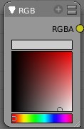
The RGB node has no inputs. It just outputs the Color currently selected in its controls section; a sample of it is shown in the top box. In the example to the right, a gray color with a tinge of red is slected.
To change the brightness and saturation of the color, LMB ![]() click anywhere within the square gradient. The current saturation is
shown as a little circle within the gradient. To change the color
itself, click anwhere along the rainbow Color Ramp.
click anywhere within the square gradient. The current saturation is
shown as a little circle within the gradient. To change the color
itself, click anwhere along the rainbow Color Ramp.
Texture Node
A texture, from the list of textures available in the current blend file, is selected and introduced through the value and/or color socket.
| Library: Please read up on the Blender Library system for help on importing and linking to textures in other blender files |
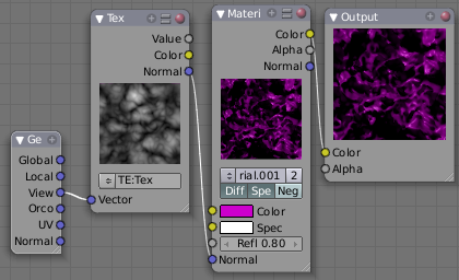
In the example to the right, a cloud texture, as it would appear to
a viewer, is added to a base purple material, giving a velvet effect.
Note that you can have multiple texture input
nodes. In the (old) panel way, multiple textures were assigned to
channels and each channel was checked on or off to be applied to the
material. With nodes, you simply add the textures to the map and plug
them into the map.
Geometry Node
The geometry node is used to specify how light reflects off the surface. This node is used to change a material's Normal response to lighting conditions.
| Note: These are exactly the same settings as in the Map Input panel for Textures, though a few settings - like Stress or Tangent - are missing here. Normally you would use this node as input for a Texture Node. |
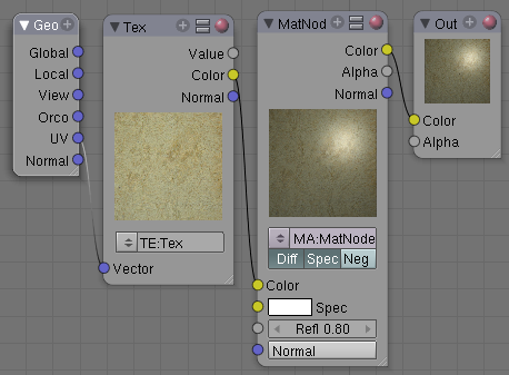
Geometry Node Example using a UV image
E.g.: To render an UV-mapped image, you would use the UV output and plug it into the Vector
Input of a texture node. Than you plug the color output of the texture
node into the color input of the material node - which corresponds to
the setting on the Map To panel.
Material Output Nodes
At any point, you may want to see the work in progress, especially right after some operation by a node. Simply create another thread from the output socket of the node to the picture input socket of an Output node to see a mini-picture.
Connect the alpha channel to see transparency. TODO: Hmmm...I wonder if you can actually see transparency....
| Effective Output Node: The only Output node that is used for the Material in the end (i.e the only non-Previw) has a little red sphere on the upper right. |
Material Color Nodes
These nodes play with the colors in the material. The choices are:
- Mix
- RGB Curves
Mix Node
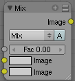
This node mixes two colors together by working on the individual and corresponding pixels in the two images or surfaces. The way the output image or material is produced is selected in the menu. There are two ways to express a color: RGB or HSV. RGB stands for the Red,Green,Blue pixel format, and HSV stands for Hue,Saturation,Value pixel format.
Mixing choices include:
- Mix
- The background pixel is covered by the foreground using alpha values.
- Add
- The pixels are added together. Gives a bright result.
- The "opposite" to Subtract mode.
- Subtract
- Pixels are subtracted from one another. Gives a dark result.
- The "opposite" to Add mode.
- Multiply
- Returns a darker result than either pixel in most cases (except one of them equals white=1). Completely white layers do not change the background at all. Completely black layers give a black result.
- The "opposite" to Screen mode.
- Screen
- Both pixel values are inverted, multiplied by each other, the result is inverted again. This returns a brighter result than both input pixels in most cases (except one of them equals 0). Completely black layers do not change the background at all (and vice versa) - completely white layers give a white result.
- The "opposite" to Multiply mode.
- Overlay
- A combination of Screen and Multiply mode, depending on the base color.
- Divide
- The color of one is divided by the other. For example, a bright red pixel divided by a gray pixel results in a dark red pixel.
- Difference
- Both pixels are subtracted from one another, the absolute value is taken. So the result shows the distance between both parameters, black stands for equal colors, white for opposite colors (one is black, the other white). The result looks a bit strange in many cases. This mode can be used to invert parts of the base image, and to compare two images (results in black if they are equal).
- Darken
- Both pixels are compared to each other, the smaller one is taken. Completely white layers do not change the background at all, and completely black layers give a black result.
- Lighten
- Both parameters are compared to each other, the larger one is taken. Completely black layers do not change the image at all and white layers give a white result.
- Dodge
- Some kind of inverted Multiply mode (the multiplication is replaced by a division of the "inverse"). Results in lighter areas of the image.
- Burn
- Some kind of inverted Screen mode (the multiplication is replaced by a division of the "inverse"). Results in darker images, since the image is burned onto the paper, er..image (showing my age).
- Color
- Adds a color to a pixel, tinting the overall whole with the color. Use this to increase the tint of an image.
- Value
- The RGB values of both pixels are converted to HSV values. The values of both pixels are blended, and the hue and saturation of the base image is combined with the blended value and converted back to RGB.
- Saturation
- The RGB values of both pixels are converted to HSV values. The saturation of both pixels are blended, and the hue and value of the base image is combined with the blended saturation and converted back to RGB.
- Hue
- The RGB values of both pixels are converted to HSV values. The hue of both pixels are blended, and the value and saturation of the base image is combined with the blended hue and converted back to RGB.
The amount of mixing is selected by the Factor input field (Fac:).
Use the Mix node in combination with a mask to affect only certain areas of the image. In particular, in the old darkroom days, we used a circle cut out taped to a straw to dodge areas of the photo as the exposure was made. We would burn in an image by holding a mask over the image. The mask had a hold in it, letting light through and thus 'burning' in the image onto the paper. The same equivalent can be used here by mixing an alpha mask image with your image using a dodge mixer to lighten an area of your photo. Remember that black is zero effect, and white is one (full) effect.
RBG Curves Node
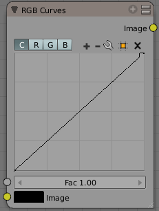
For each color component channel (RGB) or the composite (C), this node allows you to define a bezier curve that varies the input (across the bottom, or x-axis) to produce an output value (the y-axis). By default, it is a straight line with a constant slope, so that .5 along the x-axis results in a .5 y-axis output. Click and drag along the curve to create a control point and to change the curve's shape. Use the X to delete the selected (white) point.
Clicking on each C R G B
component displays the curve for that channel. For example, making the
composite curve flatter (by clicking and dragging the left-hand point
of the curve up) means that a little amount of color will result in a
lot more color (a higher Y value). Effectively, this bolsters the faint
details while reducing overall contrast. You can also set a curve just
for the red, and for example, set the curve so that a little red does
not show at all, but a lot of red does.
Here are some common curves you can use to achieve desired effects:
Material Vector Nodes
TODO: what exactly do these nodes _do_?
- Mapping
- Normal
Mapping Node
TODO: coming soon...
Normal Node
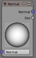
The Normal node generates a normal vector and a dot product. Click and Drag on the sphere to set the direction of the normal.
This node can be used to input a new normal vector into the mix.
For example, use this node as an input to a Color Mix node. Use an
Image input as the other input to the Mixer. The resulting colorized
output can be easily varied by moving the light source (click and
dragging the sphere).
The (face) normal is the direction of the face in relation to the camera. You can use it to do the following:
- Use this node to create a fixed direction -> output Normal.
- Calcuate the Dot-Product with the Normal-Input. The Dot-Product is a scalar value (a number).
- If two normals are pointing in the same direction the Dot-Product is zero (0).
- If they are perpendicular the Dot-Product is 1.
- If they are antiparallel (facing directly away from each other) the Dot-Product is -1. And you never thought you would use the Vector Calculus class you took in college - shame on you!
So now we can do all sorts of things that depends on the viewing angle (like electron scanning microscope effect or some of techniques described in the section Tutorials/Textures/Map Input Techniques). And the best thing about it is that you can manipulate the direction interactively.
| One caveat: The normal is evaluated per face, not per pixel. So you need enough faces, or else you don't get a smooth result |
Normal Node Example
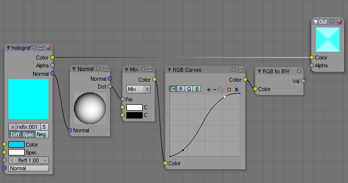
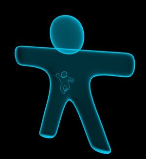
In the shown example the Dot-Product is used to govern the Alpha-Value of the material. The RGB Curves node is used to sharpen the blend between black and white (which results in a range from fully transparent to fully opaque).
The material is an ordinary blue/cyan material with a high Emit value and Z-Transp
activated; the background is black. So, as the face angle gets closer
to pointing directly at the camera, the material gets more transparent.
As the face gets closer to pointing at a right angle to the camera (in
this case facing up or down), it gets more opaque.
Using Normal to reflect bumpy-looking textures
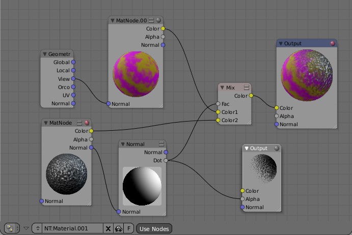
We can use the Normal node to shift the reflection, and thus the shinyness, of a material as shown below. This effect can also be done without nodes, using the materials and texture panels. However, using Nodes allows you to graphically see what is going on to create the final material. The result is that, even though the surface mesh in your model is physically smooth, the reflection makes it look like it has a very fine bumpyness or uneven coating to it, like a really bad paint job or surface prep job was done. This is key to making realistic-looking surfaces.
This map starts out using the geometry node to modify a base material called MatNode.001, shown in the header as MatNode.00 (the "1" was cut off to make the Node skinny, which may happen to you). The Geometry node puts out the View vector set, which flattens the color (removes any shine). MatNode.001 is itself a base tan color with a marble texture that affects and mixes in a purple where the texture is black.
A second material, MatNode, which is the default gray color with a noise texture, is routed through our handy Normal node. The ball has been rolled up and to the right. That puts out a mask that you can see in the Output viewer that is showing the Dot product output. Mixing that mask with the marbleized color and noise material/texture creates the final output for Material.001. As an exercise for the reader, giving the MatNode a color (instead of the grey) would create a specularity effect.
Material Convertor Nodes
As the name implies, these nodes convert the colors in the material in some way.
ColorRamp Node
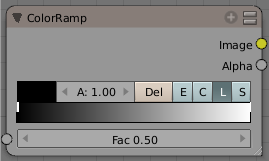
The ColorRamp Node is used for mapping values to colors with the use of a gradient. It works exactly the same way as a colorband for textures and materials, using the Factor value as a slider or index to the color ramp shown, and outputting a color value and an alpha value from the output sockets.
By default, the ColorRamp is added to the node map with two
colors at opposite ends of the spectrum. A completely black black is on
the left (Black as shown in the swatch with an Alpha value of 1.00) and a whitewash white is on the right. To select a color, LMB ![]() click on the thin vertical line/band within the colorband. The example
picture shows the black color selected, as it is highlighted white. The
settings for the color are shown above the colorband as (left to
right): color swatch, Alpha setting, and interpolation type.
click on the thin vertical line/band within the colorband. The example
picture shows the black color selected, as it is highlighted white. The
settings for the color are shown above the colorband as (left to
right): color swatch, Alpha setting, and interpolation type.
To change the hue of the selected color in the colorband, LMB ![]() click on the swatch, and use the popup color picker control to select a new color. Press enter to set that color.
click on the swatch, and use the popup color picker control to select a new color. Press enter to set that color.
To add colors, hold Ctrl down and Ctrl LMB ![]() click inside the gradient. Edit colors by clicking on the rectangular
color swatch, which pops up a color-editing dialog. Drag the gray
slider to edit A:lpha
values. Note that you can use textures for masks (or to simulate the
old "Emit" functionality) by connecting the alpha output to the factor
input of an RGB mixer.
click inside the gradient. Edit colors by clicking on the rectangular
color swatch, which pops up a color-editing dialog. Drag the gray
slider to edit A:lpha
values. Note that you can use textures for masks (or to simulate the
old "Emit" functionality) by connecting the alpha output to the factor
input of an RGB mixer.
To delete a color from the colorband, select it and press the Delete button.
When using multiple colors, you can control how they transition from one to another through an interpolation mixer. Use the interpoloation buttons to control how the colors should band together: Ease, Cardinal, Linear, or Spline.
Use the A: button to define the Alpha value of the selected color for each color in the range.
RGB to BW Node
This node converts a color image to black-and-white.
| Connecting Output Socket: When you connect the output Val socket to an input socket that excepts an Image, Blender automatically inserts a ColorRamp node, to translate the output value to a material color. |
Groups of Nodes
Node maps can get quite complex. Blender allows you to group a set of nodes together to both save space and help you conceptualize what the net effect of a mini-map does to a material/image. This menu selection shows the names of the groups of nodes that you have defined. Select any one to add that group to the map.
Create a Node Group
A group is created by Shift-clicking all the nodes you want in the group, and then selecting Node -> Make Group (Ctrl G). The group node is shown with a green bar, and the name is shown in an editable field (Shift-click on the name to enter EditMode and change the name to something that represents what that group does. The input sockets to the group is the input sockets of contained nodes, and akin for output(s).
Editing Node Groups
You can select the group and press Tab (or select Node -> Edit Group) to enter/leave the group.
Ungroup Nodes
You can select the group and press Alt G (or select Node -> Ungroup) to conver the grouped nodes back to normal.
|
