Manual/Meshes
From BlenderWiki
Contents[hide] |
EditMode
You can work with geometric objects in two modes: ObjectMode and EditMode. Operations in ObjectMode affect whole objects, and operations in EditMode affect only the geometry of an object, but not its global properties such as location or rotation. You switch between these two modes with the TAB key.
ObjectMode is recognizable if you see the following header in the 3D view:
EditMode is recognizable if you see the following header in the 3D view:
After creating an object you are immediately placed in EditMode. EditMode only works on one object at a time, the active object. An object outside EditMode (i.e. ObjectMode) is drawn in purple in the 3D Windows (in wireframe mode) when selected; it is black otherwise.
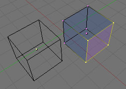
In EditMode each vertex is drawn in purple, each edge is drawn in black and each face is drawn in translucent dark-blue. In (One cube selected) the Cube on the right is in EditMode. The Cube on the left is in ObjectMode and not selected. Each selected vertex or edge is highlighted in yellow.
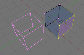
If multiple objects are selected and EditMode is entered then the last Object selected (the Active Object) enters EditMode. The other Objects remain purple and in ObjectMode. As shown in (Two Cubes selected prior to EditMode), both cubes were selected prior to EditMode and now the left cube is still purple and the right cube (the Active object) is in EditMode.
If enough vertices are selected to form a face then that face is
highlighted in translucent purple while the remaining faces are
highlighted in translucent dark-blue. This helps give you a frame of
reference when selecting vertices, edges or faces. The translucent
effect indicates that you have selected enough vertices to imply one or
more faces. See Edge and Face Tools for further details on implicit selections.
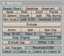
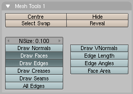
If the Buttons Window is visible and Editing (F9) is activated then two panels appear while in Edit Mode (Mesh Tools and Mesh Tools 1):
By default the buttons (Draw Faces and Draw Edges) are pre-selected and any selected edges and faces are highlighted.
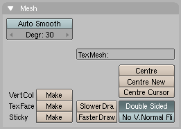
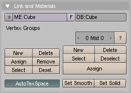
In addition, panels (Link and Materials and Mesh) are updated.
The Link and Materials panel gains the New, Delete, Assign, Remove, Select and Desel. buttons. The Mesh panel loses the Decimator, Apply and Cancel group of buttons.
Basic Editing
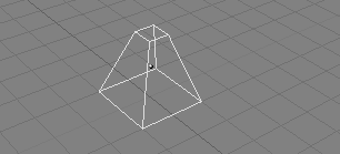
Most simple operations from Object mode (like selecting, moving, rotating, and scaling) work the same way on vertices as they do on objects. Thus, you can learn how to handle basic Edit mode operations very quickly. The only notable difference is a new scaling option, Alt S which scales the selected vertices along the direction of the normals (shrinks-fattens). The truncated pyramid in (Chopped-off pyramid), for example, was created with the following steps:
- Add a cube to an empty scene. If not in Edit mode then use TAB to enter Edit Mode.
- Make sure all vertices are deselected (purple). Use border select (B) to select the upper four vertices.
- Check that the scaling center is set to anything but the 3D cursor (you don't want to see
 as the selected pivot point), then switch to scale mode (S), reduce the size, and confirm with LMB.
- Exit EditMode by pressing TAB.
All operations in Edit mode
are ultimately performed on the vertices; the connected edges and faces
automatically adapt, as they depend on the vertices' positions. To
select an edge, you must select the two endpoints or place the mouse on
the edge and press Alt RMB ![]() . To select a face, each corner must be selected.
. To select a face, each corner must be selected.
Edit mode operations are many, and most are summarized in the Editing Context Buttons window, accessed via the (![]() ) header button or via F9 (Edit Context.).
) header button or via F9 (Edit Context.).
Mirror Axis and Modifier
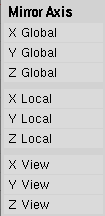
One extra feature for Edit mode is the Mirroring tool. If you have some vertices selected and you press M you will be presented with a Menu containing nine options (Mirror Axis). You can select from these to mirror the selected vertices with respect to any of the X, Y or Z axes of the Global, Local, or Viewing reference. If you need to select groups of vertices use the handy CircleSelect tool.
| Editor's Note: There is a much more advanced tool for performing mirroring operations and that is the Mirror Modifier |
Specials
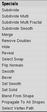
With W you can call up the Specials menu in Edit mode (Specials Menu.). With this menu you can quickly access functions which are frequently required for polygon-modelling.
- Subdivide - Each selected edge is split in two, new vertices are created at middle points, and faces are split too, if necessary.
- Subdivide Multi - This is identical to Subdivide except a dialog pops up asking for the number of cuts or repeated subdivisioning. The default is "2".
- Subdivide Multi Fractal - As above, but new vertices are randomly displaced within a user-defined range.
- Subdivide Smooth - Same as Subdivide, but new vertices are displaced towards the barycenter (centre of mass) of the connected vertices.
- Merge - Merges selected vertices into a single one, at the barycenter position or at the 3D cursor position.
- Remove Doubles - Merges all of the selected vertices whose relative distance is below a given threshold (0.001 by default).
- Hide - Hides selected vertices.
- Reveal - Shows hidden vertices.
- Select Swap - All selected vertices become unselected and vice-versa.
- Flip Normals - Change the Normal directions of the selected faces.
- Smooth - Smooths out a mesh by moving each vertex towards the barycenter of the linked vertices.
- Bevel - Bevels the entire object regardless of the selected vertices, edges or faces. See Manual/Edge_and_Face_Tools#Bevel
- Set Smooth - Changes the selected faces to smoothing shading.
- Set Solid - Changes the selected faces to faceted or flat shading.
| Keyboard Tip: You can access the entries in a PopupMenu by using the corresponding numberkey. For example, pressing W and then 1 will subdivide the selected edges without you having to touch the mouse at all. |
Many of these actions have a button of their own in the Mesh Tools panel "link here" of the Edit Buttons Window (Edit Context.). The Remove doubles threshold can be adjusted on that panel too.
Mesh Undo
Blender has a global undo system, giving full multiple level undo capabilities in all areas of Blender. Exceptions are: Edit mode Armature, and Fileselect, Audio and Oops windows.
The new global hotkey for undo is Ctrl Z, and Shift Ctrl Z for redo.
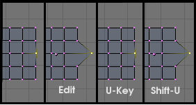
Mesh undo works in the background saving copies of your mesh in memory as you make changes. Pressing the U in mesh EditMode reverts to the previously saved mesh, undoing the last edit operation (Undo and Redo).
Mesh Undo operations are only stored for one mesh at a
time. You can leave and re-enter EditMode for the same mesh without
losing any undo information, but once another mesh is edited, the undo
information for the first is lost. Pressing Shift U re-does the last undo operation (Undo and Redo).
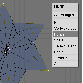
Pressing Alt U brings up the Undo Menu (Undo Menu). This lists all the undo steps by name so you can quickly find your way back to a known good point in your work. The Undo menu also contains the option All Changes. This option is more powerful than merely pressing U
repeatedly, and will reload the mesh data as it was at the beginning of
your edit session, even if you have used up all your undo steps.
Mesh Undo has the potential to be very memory intensive. A
mesh of 64,000 faces and verts can use over 3MBs of RAM per undo step!
If you are on a machine that is strapped for RAM (Memory), in the User
reference Window under Edit Methods, there is a NumButton (Editmode undo) for setting the maximum number of undo steps saved see (User Preferences/Edit Methods). The allowable range is between 1 and 64. The default is 32.
|
