Manual/Using Nodes
From BlenderWiki
Contents[hide] |
Please only proceed after reading Node Editor. You need to be in the Node editor window in order to follow the text below.
Node Basics
What are nodes
"Nodes" (some people call connected nodes "noodles") are individual blocks that perform a certain operation on zero or more inputs or outputs. Some nodes, like the Value or RGB nodes, only output a value. Other nodes, such as the RGB Curves node, take in an image, and output a modified copy. Other nodes, such as the Defocus Node or Vector Blur node, perform even more complex tasks.
Adding and Arranging Nodes
Nodes are added in two ways to the node editor window:
- By clicking the Add menu in the node editor toolbar and picking the type of node you want, or
- By having your cursor in the node editor window and pressing Space and picking a node from the popup Add menu.
In general, try to arrange your nodes within the window such that the image flows from left to right, top to bottom. Move a node by clicking on a benign area and dragging it around. The node can be clicked almost anywhere and dragged about; connections will reshape as a bezier curve as best as possible.
| Threads beneath Nodes: Threads (the curves that connect sockets) may reposition behind a node; however they are just that and do not interact with that node in any way. |
Sockets
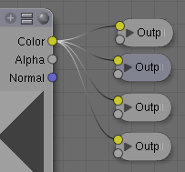
Each Node in your node window will have "sockets" (often also
referred to as "connectors") which are small colored circles to which
input data and output data will be linked (Node Sockets).
There are three colors:
-
 Yellow sockets
- Indicates that color information needs to be input or will be output from the node.
-
 Grey sockets
- Indicates values (numeric) information. It can either be a single numerical value or a so-called "value map" (you can think if a value map as a grayscale-map where the different amount of bright/dark refelcts the value for each point.) If a single value is used as an input for a "value map" socket all points of the map are set to this same value.
- Common use: Alpha maps and value-options for a node.
-
 Blue/Purple sockets
- Indicates vector/coordinate/normal information.
Between nodes, yellow must be linked to yellow, gray to gray, blue to blue, unless you use a converter which we'll cover later on.
Next to the color in the node you will see the name of that socket. Though not always the case, you can see the name of the socket as what the information is intended to be, not necessarily what it has to be - for example, I can add a link from an gray socket titled Alpha to the material node's gray Reflection socket and still get a result, they key thing being that it's a gray to gray connection.
There are exceptions where you can mix yellow (e.g. a color-image) and gray (e.g. grayscale) without convertors, Blender normally places a convertor if needed, so feel free to experiment with them. You can use the "Viewer" output nodes as explained in the later sections to see if/how it works.
Connecting and Disconnecting Sockets
You link between sockets by clicking the socket with the LMB ![]() and holding to drag the thread to another socket, you then let go once
you reach the corresponding socket. To break a link between sockets
click the LMB
and holding to drag the thread to another socket, you then let go once
you reach the corresponding socket. To break a link between sockets
click the LMB ![]() and hold and drag a box around any part (it can be really small) to
break the link. From output sockets, multiple threads can be extracted
and attached to many nodes (Node Linking).
and hold and drag a box around any part (it can be really small) to
break the link. From output sockets, multiple threads can be extracted
and attached to many nodes (Node Linking).
In this case, a copy of each output is routed along a thread. However, only a single thread can be linked to an input socket.
Grouping Nodes
Both material and composite nodes can be grouped. Grouping nodes can simplify the node network layout in the node editor, making your material or composite node network easier to work with. Grouping nodes also creates what are called NodeGroups (inside a .blend file) or NodeTrees (when appending).
If you have created a material using nodes that you would like to use in another .blend file, you can simply append the material from one .blend file to another.
However, what if you would like to create a new material, and use a branch from an existing material node network? You could re-create the branch. Or you could append the material to the new .blend file, then cut and paste the branch that you want into the new material. Both of these options work, but are not very efficient when working across different .blend files.
What if you have created a “Depth of Field” composite node network and would like to use it in another .blend file? Here again, you could re-create the network, but this is not very efficient.
A better method of re-use for either material node branches or composite node networks would be to create groups of nodes. These groups will then be made available through the standard appending method.
To create a node group, in the node editor, select the nodes you want to include, then press Ctrl G or Space…node…make group. A node group will have a green title bar. All of the selected nodes will now be minimized and contained within the group node. Default naming for the node groups is NodeGroup, NodeGroup.001 etc. There is a name field in the node group that will allow you to change the name of the group. Change the name of the node group to something meaningful. When appending node groups from one .blend file to another, Blender does not make a distinction between material node groups or composite node groups, so I recommend some naming convention that will allow you to easily distinguish between the two types. For example, name your material node branches Mat_XXX, and your composite node networks Cmp_XXX.
What NOT to include in your groups. Material node groups should not include material nodes or output nodes. If you include a material node in your group, you will end up having the material node appear twice, once inside the group, and once outside the group in the new material node network. If you include an output node in the group, there will not be an output socket available from the group.
Composite node groups should not include a render layers node (Blender wont let you), or a composite node. Here again, if you include a composite node, there will not be an output socket available from the group.
Once you have appended a NodeTree to your .blend file, you can make use of it in the node editor by pressing Space...Add...Groups, then select the appended group.
Node Controls
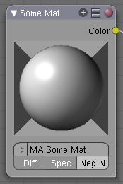
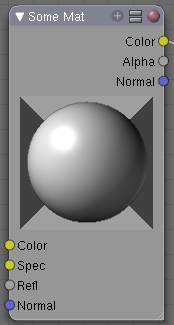
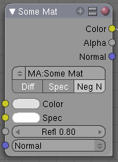
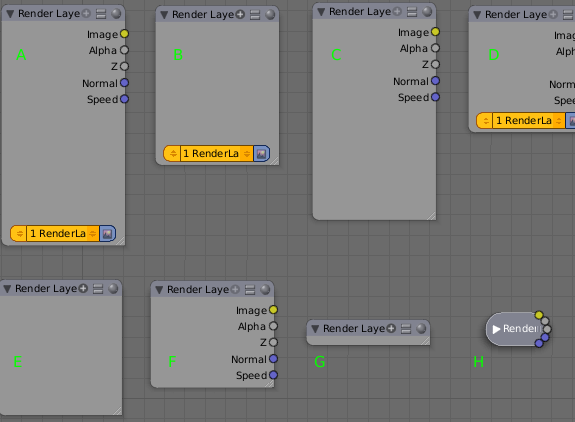
At the top of a node there are up to 4 visual controls for the node (Top of a Node). Clicking these controls influences how much information the node shows.
-

 Arrow
Arrow
- The arrow on the left collapses the node entirely (Collapsing Arrow).
-

 Plus sign (+)
- The "plus" icon collapses all sockets that do not have a thread connected to it (Plus Sign).
-
 Two squares (=) or "Equal sign"
- The icon with the two squares collapse all the items in a node that have boxes with information in them (Menu Collapse).
-

 Sphere
- The sphere icon collapses the viewing window (if the node has one) (Sphere).
- If the Spere is red this can have 3 reasons:
- It's the only effective output Composite node in the compositor.
- It's the only effective material Output node (the first one that is added).
- If it's a Material input node that has a Material (MA:) assigned to it.
The latter three can be used in varying combinations with each
other. The arrow that collapses the entire node can only be used in
combination with the plus sign (In Combination).
Node Sizing
Fine Sizing of an individual node can also be accomplished somewhat by clicking LMB ![]() and dragging in the lower right-hand corner (where the little slanted lines are).
and dragging in the lower right-hand corner (where the little slanted lines are).
Node Curves
Some nodes have a curve area that translates an input value to an output value. You can modify this curve shape by clicking on a control point and moving it, or adding a control point. Some examples are shown below:
Every curve starts out as a straight line with a slope of 1. (My
daughter NEVER thought she would use her high school algerbra. Ha!) The
curve starts out with two tiny black control points at each end of the
line. Clicking LMB ![]() on a control point selects it and it turns white.
on a control point selects it and it turns white.
Changing the curve affects how the output is generated. The input, X, usually proceeds linerally (at regular intervals) across the bottom axis. Go up until you hit the curve, and then over to the right to determine the Y output for that corresponding X. So, for the second example, as X goes from 0 to 1.0 across the bottom, Y varies from 0.0 to 0.5. In the third, as X goes from 0.0 to 1.0 across the bottom, Y stays constant at 0.5. So, in the picture above, these curves have the following affect on time: A don't affect, B slow down, C stop, D accellerate, and E reverse time.
The "Curves" widget is a built-in feature in Blender's UI, and can be used anywhere, provided the curve data itself is being delivered to this widget. Currently it is in use in the Node Editor and in the UV Window.
This widget will map an input value horizontally and return the new value as indicated by the height of the curve.
RGB Curves
Multiple curves can be edited in a single widget. The typical use, RGB curves, has "Combined" result or "Color" ("C") as the first curve, and provides curves for the individual R, G, and B components. All four curves are active together, the "C" curve gets evaluated first.
Selecting curve points
- LMB
 always selects 1 point and deselects the rest.
- Hold Shift while clicking to extend the selection or select fewer points.
Editing curves
- LMB
 click&drag on a point will move points.
- A LMB
 click on a curve will add a new point.
- Dragging a point exactly on top of another will merge them.
- Holding Shift while dragging snaps to grid units.
- Ctrl RMB
 adds a point.
- Use the X icon to remove selected points.
Editing the view
The default view is locked to a 0.0-1.0 area. If clipping is set, which is default, you cannot zoom out or drag the view. Disable clipping with the icon resembling a #.
Special tools
The wrench icon gives a menu with choices to reset a view, to define interpolation of points, or to reset the curve.
|

