Manual/Using the 3D View
From BlenderWiki
Contents[hide] |
Perspective and Orthographic Projection
Mode: All Modes
Hotkey: NumPad 5
Menu: View → Perspective/Orthographic
Description
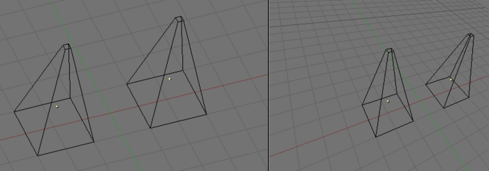
Each 3D Viewport supports two different types of projection. These are demonstrated in (Orthographic (left) and perspective (right) projection.):
Our eye is used to perspective viewing because distant objects appear smaller. Orthographic projection often seems a bit odd at first, because objects stay the same size independent of their distance; It is like viewing the scene from an infinitely distant point. Nevertheless, orthographic viewing is very useful (it is the default in Blender and most other 3D applications), because it provides a more "technical" insight into the scene, making it easier to draw and judge proportions.
Options
To change the projection for a 3D Viewport, choose the View>>Orthographic or the View>>Perspective Menu entry (A 3D Viewport's view menu.). The hotkey NumPad 5 toggles between the two modes.
| Camera projection: Changing the projection for a 3D Viewport does not affect the way the scene will be rendered. Rendering is in perspective by default. If you need to create an Orthographic rendering, select the camera and press Ortho in the EditButtons (F9) Camera Panel. |
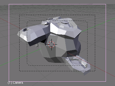
The View>>Camera Menu entry sets the 3D Viewport to camera mode (Hotkey: NumPad 0). The scene is then displayed as it will be rendered later (see Demonstration of camera view.): the rendered image will contain everything within the outer dotted line. Zooming in and out is possible in this view, but to change the viewpoint, you have to move or rotate the camera.
Technical Details
Perspective definition
A Perspective view is geometrically constructed this way: you have a scene in 3D and you are an observer placed at a point O. The 2D perspective scene is built by placing a plane, a sheet of paper where the 2D scene is to be drawn in front of point O, perpendicular to the viewing direction. For each point P in the 3D scene a line is drawn, passing from O and P. The intersection point S between this line and the plane is the perspective projection of that point. By projecting all points P of the scene you get a perspective view.
Orthographic definition
In an orthographic projection, also called "orthonormal", you have a viewing direction but not a viewing point O. The line is then drawn through point P so that it is parallel to the viewing direction. The intersections S between the line and the plane is the orthographic projection. And by projecting all point P of the scene you get the orthographic view.
View Shading
Mode: All Modes
Hotkey: Z / Shift Z / Alt Z / D
Description
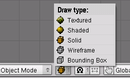
Depending on the speed of your computer, the complexity of your Scene, and the type of work you are currently doing, you can switch between several drawing modes:
- Textured Alt Z
- Displays UV image textured models with OpenGL lighting. Procedural textures will not be shown.
- Shaded Shift Z
- Approximates all textures and lighting at each vertex, and blends from one to the next. Much less accurate than using the render engine to check textures, but much faster. Note that if you have no lighting in your scene, everything will remain black.
- Solid Z or Alt Z
- Surfaces are drawn as solid colours, with built-in OpenGL lighting (not dependent on scene light sources)
- Wireframe Z or Shift Z
- Objects only consist of lines that make their shapes recognizable. This is the default drawing mode.
- Bounding Box
- Objects aren't drawn at all; instead, this mode shows only the rectangular boxes that correspond to each object's size and shape.
You can also pop up a contextual menu by pressing D to toggle between all the draw modes
Local View
Mode: All Modes
Hotkey: NumPad /
Menu: View → Local View
Description
When in local view, only the selected objects are displayed, which can make editing easier in complex scenes. To enter local view, first select the objects you want (see Selecting objects) and then use the View>>Local View Menu entry; use the View>>Global View Menu entry to go back to Global View. (A 3D Viewport's view menu.). The hotkey NumPad / toggles between Local and Global View.
View Clipping Border
Mode: Any mode
Hotkey: Alt B
Menu: View → Set Clipping Border
Description
To assist in the process of working with complex models and scenes, you can change the view clipping to visually isolate what you're working on.
Using this tool you create a 3D clipping volume shaped liked a Pyramid; you could think of it as a Frustum with a top. You specify the base of the Pyramid by creating a 2D rectangular region.
Examples
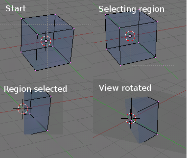
(Region/Volume clipping) is an example of using the clipping tool with a cube.
Start by activating the tool with Alt B, see "Start" in the upper left. This will generate a dashed cross-hair cursor. Click with the LMB ![]() and drag out a rectangular region shown in the upper right. Now a
region is defined and clipping is applied against that region in 3D
space. Notice that part of the Cube is now invisible or clipped. Use
the MMB
and drag out a rectangular region shown in the upper right. Now a
region is defined and clipping is applied against that region in 3D
space. Notice that part of the Cube is now invisible or clipped. Use
the MMB ![]() to rotate the view and you will see that only what is inside the
Pyramid volume is visible. All Edge/Face tools still function as normal
but only within the Pyramid volume.
to rotate the view and you will see that only what is inside the
Pyramid volume is visible. All Edge/Face tools still function as normal
but only within the Pyramid volume.
The gray area surrounding the volume is the Pyramid volume itself. To deactivate the clipping tool toggle it by applying Alt B a second time. All of 3D space will become visible once again.
|


